
Process Planning and Execution on the Shop Floor
Is your manufacturing process really clear for operators?
How can you ensure operators follow the correct manufacturing process ?
Standardise your shop floor working methods and improve quality and productivity.
During this post, we will look at the commonly used methods to communicate manufacturing information to the shop floor operators and how effective they are in terms of ensuring a consistent high quality product.
There are generally three main types of information:
- 1. Process plan – A description of the process flow and the sequence of manufacturing operations.
- 2. Method instructions – How to execute the operations (what, how, who etc.)
- 3. Validation – Record of manufacturing (checks, measurements, traceability etc.)
1. Process Plan
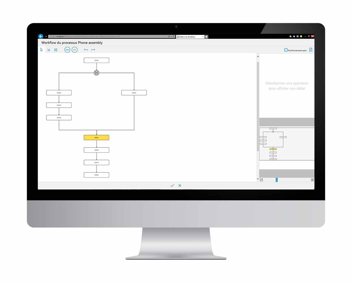
The process plan simply defines manufacturing operations and the order in which they should be carried out. This could simply be a printed document or be created within the company manufacturing software. As well as communicating the order in which the operations should be done, a key use of the process plan is to monitor progress and ‘track’ the position of products within the process.
Therefore, the process plan is often created in the company ERP system. Within the ERP system, each operation is a ‘cost centre’ and has defined resources.
From the operators point, the plan is either viewed on a shop floor PC or a printed paper copy. After each operation is completed, the operation is normally marked as complete and ‘closed’.
Advantage of ERP or MES based process plan
- Plan is integrated with other business resources – material, people, planning, cost analysis, etc.
Disadvantages of ERP based process plan
- Lack of detail– on one hand, being integrated with the business system is beneficial but on the other, this normally means that the plan lacks detail and provides only high level description of tasks for the operator
- Lack of flexibility– ERP plans are fine for creating a simple sequential process but are often not capable of modelling more complex process where there are parallel machines and operations or when tasks need to be ‘moved’ within the process due to day-day problems.
2. Instructions
Closely linked with the process plan are the operators working instructions which describe how to execute the operation. The content and format of the work instructions are critical and can have a huge impact on the product quality. Some industries (e.g. automotive) focus heavily on this point and many OEM companies have set standards for suppliers.
The work instruction is so important because it is a critical tool for standardising working methods which is a key factor in assuring consistent product quality.
A good work instruction should:
- Define each individual step in the operation
- Clearly describe the method to complete each task (using text/images/videos)
- Define the required tools and resources
- Define safety and protective measures
- Define any checks or measurements which need to be conducted and recorded
- What to do if check or measurement is out of specification (reaction plan)
However, within and across industries, there is a huge range in the quality of instructions provided to the operators.
It is not uncommon to see many different documents presented to the operator which are not specific to the operation. It is then left to the operator to ‘decipher’ or ‘interpret’ the documents which leads to many different working methods and a big chance errors.
Common issues with work instructions include:
- No single instruction. The information for each operation is presented to the operator using various generic process documents which they have to interpret! This leads to many different working methods and total lack of standardisation;
- No standard layout for document and information not presented in a user friendly format;
- Operation not broken down into clear individual tasks;
- Not enough detail in the method description.
Improving the quality of work instructions and hence standardising working methods is one of the key areas which will immediately have an impact on improving quality and reducing waste.
3. Validation
Finally, we must be able to demonstrate (to our customers & regulatory bodies) that our products meet the design requirements and were manufactured under controlled process parameters. Therefore we must measure and record both our product and process characteristics. This data is also used by engineers to analyse and optimise process performance as well as the operators themselves if SPC (statistical process control) is used.
The most common method for recording this data is using a paper ‘check or inspection sheet’
The main issues with paper records are that:
- They must be controlled and stored;
- The information held in them must be easily retrievable.
Unfortunately, this is not as easy as it sounds and sometimes records are lost or stored where they cannot easily be retrieved. Additionally, data analysis of paper records is difficult and time consuming.
The missing link
As you can see, there are many problems associated with these commonly used ‘execution’ methods on the shop floor. Also, the three areas described above should not be viewed as independent tasks as they are all linked.
Many of these problems occur because the overall system is not designed with the shop floor and operator at the centre. The reality is that the components of the system are effectively independent resulting in a process which is disjointed, confusing for the operator and not effective.
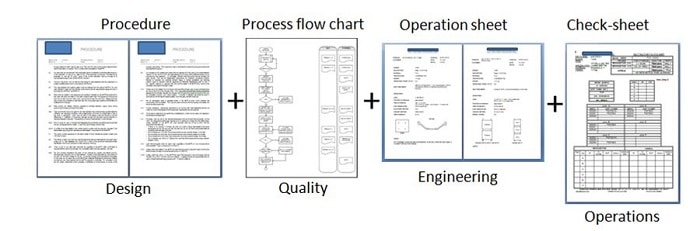
The documents and manufacturing information will always come from different sources, for example:
- IT system = IT
- Process procedures = Design engineering
- Manufacturing plan = Manufacturing engineering
- Work instructions = Manufacturing engineering
- Process flow charts = Quality
- Check sheets = Operations
Bringing it all together
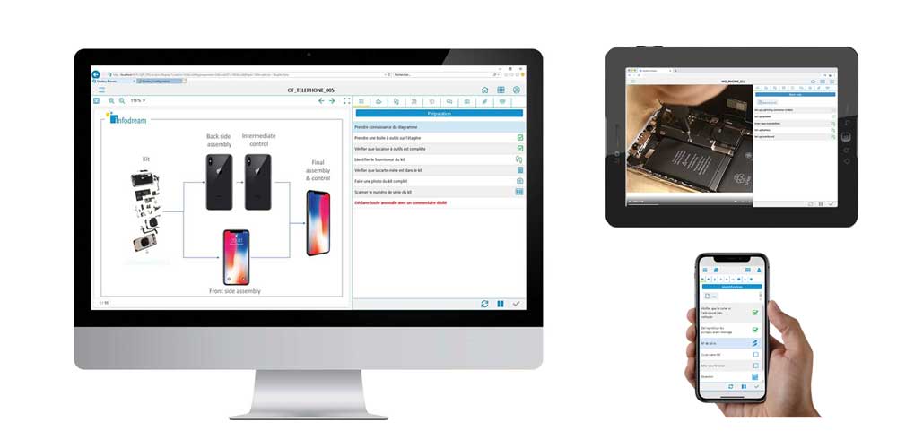
The key is to integrate all the information in a way which is structured and clear for the operators.
There are numerous software solutions available to do this.
A good system should be capable of:
- Accurately modelling the process flow including parallel working and partial processes for re-work
- Display and track progress of the product through the process
- Cater for multiple user profiles (needed for validation of critical operations)
- Identify when there are issues and the product is ‘blocked’
- Clearly display step by step dynamic instructions with low level detail and pictures/video
- Show all resources required for the current operation
- Be able to record and store checks/measurements and traceability for each step
- Provide a complete manufacturing record – what, when, who, etc.
- Store all data in a central database for easy data mining and analysis
- Remove the need for any paperwork on the shop floor
- Be able to integrate with other business systems such as ERP or MES
Ben Allister
CT Infodream Ltd
Sources : The screenshots were done using the software: Qual@xy Process